The Base Station Subsystem is composed of two parts, the Base Transceiver Station (BTS) and the Base Station Controller (BSC). These communicate across the standardized Abis interface, allowing (as in the rest of the system) operation between components made by different suppliers.
Base Transceiver Station(BTS): houses the radio tranceivers that define a cell and handles the radio-link protocols with the Mobile Station.
Base Station Controller(BSC): manages the radio resources for one or more BTSs. It handles radio-channel setup, frequency hopping, and handovers, as described below. The BSC is the connection between the mobile station and the Mobile service Switching Center (MSC).
Mobile services Switching Center(MSC):the central component of the Network Subsystem . It acts like a normal switching node of the PSTN or ISDN, and additionally provides all the functionality needed to handle a mobile subscriber, such as registration, authentication, location updating, handovers, and call routing to a roaming subscriber. These services are provided in conjuction with several functional entities, which together form the Network Subsystem. The MSC provides the connection to the fixed networks (such as the PSTN or ISDN).
The Home Location Register (HLR) and Visitor Location Register (VLR), together with the MSC, provide the call-routing and roaming capabilities of GSM.
Home Location Register (HLR): contains all the administrative information of each subscriber registered in the corresponding GSM network, along with the current location of the mobile. The location of the mobile is typically in the form of the signalling address of the VLR associated with the mobile station. There is logically one HLR per GSM network, although it may be implemented as a distributed database.
Visitor Location Register (VLR): contains selected administrative information from the HLR, necessary for call control and provision of the subscribed services, for each mobile currently located in the geographical area controlled by the VLR. Although each functional entity can be implemented as an independent unit, all manufacturers of switching equipment to date implement the VLR together with the MSC, so that the geographical area controlled by the MSC corresponds to that controlled by the VLR, thus simplifying the signalling required. Note that the MSC contains no information about particular mobile stations --- this information is stored in the location registers.
The other two registers are used for authentication and security purposes.
Equipment Identity Register (EIR): is a database that contains a list of all valid mobile equipment on the network, where each mobile station is identified by its International Mobile Equipment Identity (IMEI). An IMEI is marked as invalid if it has been reported stolen or is not type approved.
Authentication Center (AuC): is a protected database that stores a copy of the secret key stored in each subscriber's SIM card, which is used for authentication and encryption over the radio channel.
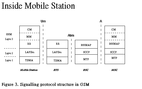
The signalling protocol in GSM is structured into three layers , as shown in Figure 3. Layer 1 is the physical layer, which uses the channel structures discussed above. Layer 2 is the data link layer. Across the Um interface, the data link layer is a modified version of the LAPD protocol used in ISDN, called LAPDm. Layer 3 of the GSM signalling protocol is itself divided into 3 sublayers.
Controls the setup, maintenance, and termination of radio and fixed channels, including handovers.
Manages the location updating and registration procedures, as well as security and authentication.
Handles general call control, and manages Supplementary Services and the Short Message Service.
The radio resources management (RR) layer oversees the establishment of a link, both radio and fixed, between the mobile station and the MSC. The RR layer is concerned with the management of an RR-session , which is the time that a mobile is in dedicated mode, as well as the configuration of radio channels including the allocation of dedicated channels.
An RR-session is always initiated by a mobile station through the access procedure, either for an outgoing call, or in response to a paging message. The details of the access and paging procedures, such as when a dedicated channel is actually assigned to the mobile, and the paging sub-channel structure, are handled in the RR layer. In addition, it handles the management of radio features such as power control, discontinuous transmission and reception, and timing advance.
Handover
In a cellular network, the radio and fixed links required are not permanently allocated for the duration of a call. Handover, or handoff as it is called in North America, is the switching of an on-going call to a different channel or cell. The execution and measurements required for handover form one of basic functions of the RR layer.
There are four different types of handover in the GSM system, which involve transferring a call between:
Channels (time slots) in the same cell
Cells (Base Transceiver Stations) under the control of the same Base Station Controller (BSC),
Cells under the control of different BSCs, but belonging to the same Mobile services Switching Center (MSC), and
Cells under the control of different MSCs.
The first two types of handover, called internal handovers, involve only one Base Station Controller (BSC). To save signalling bandwidth, they are managed by the BSC without involving the Mobile services Switching Center (MSC), except to notify it at the completion of the handover. The last two types of handover, called external handovers, are handled by the MSCs involved.
Handovers can be initiated by either the mobile or the MSC (as a means of traffic load balancing). During its idle time slots, the mobile scans the Broadcast Control Channel of up to 16 neighboring cells, and forms a list of the six best candidates for possible handover, based on the received signal strength. This information is passed to the BSC and MSC, at least once per second, and is used by the handover algorithm.
The Mobility Management layer (MM) is built on top of the RR layer, and handles the functions that arise from the mobility of the subscriber, as well as the authentication and security aspects. Location management is concerned with the procedures that enable the system to know the current location of a powered-on mobile station so that incoming call routing can be completed.
A powered-on mobile is informed of an incoming call by a paging message sent over the PAGCH channel of a cell. One extreme would be to page every cell in the network for each call, which is obviously a waste of radio bandwidth. The other extreme would be for the mobile to notify the system, via location updating messages, of its current location at the individual cell level. This would require paging messages to be sent to exactly one cell, but would be very wasteful due to the large number of location updating messages. A compromise solution used in GSM is to group cells into location areas. Updating messages are required when moving between location areas, and mobile stations are paged in the cells of their current location area.
Since the radio medium can be accessed by anyone, authentication of users to prove that they are who they claim to be, is a very important element of a mobile network. Authentication involves two functional entities, the SIM card in the mobile, and the Authentication Center (AuC). Each subscriber is given a secret key, one copy of which is stored in the SIM card and the other in the AuC. During authentication, the AuC generates a random number that it sends to the mobile. Both the mobile and the AuC then use the random number, in conjuction with the subscriber's secret key and a ciphering algorithm called A3, to generate a signed response (SRES) that is sent back to the AuC. If the number sent by the mobile is the same as the one calculated by the AuC, the subscriber is authenticated .
The Communication Management layer (CM) is responsible for Call Control (CC), supplementary service management, and short message service management. Each of these may be considered as a separate sublayer within the CM layer. Call control attempts to follow the ISDN procedures. Other functions of the CC sublayer include call establishment, selection of the type of service (including alternating between services during a call), and call release.
Unlike routing in the fixed network, where a terminal is semi-permanently wired to a central office, a GSM user can roam nationally and even internationally.
"GSM" has proven a success, showing that international cooperation on such projects between academia, industry, and government can succeed.
The availability of all communication services anytime, anywhere, to anyone, by a single identity number and a pocketable communication terminal .
The GSM system is a first approach at a true personal communication system. The SIM card is a novel approach that implements personal mobility in addition to terminal mobility. Together with international roaming, and support for a variety of services such as telephony, data transfer, fax, Short Message Service, and supplementary services, GSM comes close to fulfilling the requirements for a personal communication system: close enough that it is being used as a basis for the next generation of mobile communication technology in Europe, the Universal Mobile Telecommunication System (UMTS).
Another point where GSM has shown its commitment to openness, standards and interoperability is the compatibility with the Integrated Services Digital Network (ISDN) that is evolving in most industrialized countries, and Europe in particular (the so-called Euro-ISDN).
GSM is a very complex standard, but that is probably the price that must be paid to achieve the level of integrated service and quality offered while subject to the rather severe restrictions imposed by the radio environment.